CAESAR II: Whenever Pressure Vessel or Heat exchanger (Static Equipments) nozzle loads exceeds the allowable values provided by Vendors (Equipment manufacturer) or standard project specific tables (guidelines), the piping stress professional is permitted to use WRC 107/297 (or any other FEA) to check the stresses at the Nozzle-Shell junction point and check the stresses with allowable values provided by Codes.
WRC-107, entitled “Local Stresses in Spherical and Cylindrical Shells due to External Loadings”, was released in 1965 and updated in 1979. WRC-297 was released in 1984 and goes under the title of “Local Stresses in Cylindrical Shells due to External Loadings – Supplement to WRC Bulletin No. 107”
Assumptions & limitations for using WRC 107:
To determine whether WRC 107 bulletin can be used for local stress checking the following geometry guidelines must be met:
- Nozzle Connection is assumed to be a rectangular loading surface (no nozzle, no hole) for circular and longitudinal moment loads. In short, not for nozzle stress calculations.
- WRC 107 has no provision for pressure loads. The adding of pressure to external loads has historically been problematic for WRC 107 calculations.
- Shell reinforcements are not considered.
- WRC 107 does not provide flexibilities of the intersections
- d/D<0.33
- Dm/T=(D-T)/T>50 (Here, T=Vessel Thickness, Dm=mean diameter of vessel)
- Not intended for small D/T ratios.
Assumptions & limitations for using WRC 107:
To determine whether WRC 107 bulletin can be used for local stress checking the following geometry guidelines must be met:
- Includes effect of nozzle, nozzle opening and nozzle thickness.
- Does not include pressure effects. (See WRC 468)
- Includes stiffness calculations in Fig 59&60 that can easily be used to produce numbers that are off by several orders of magnitude (high and low) since extrapolation on log-log plot is required for geometric parameters.
- Shell reinforcements are not considered.
- d/D<=0.5
- d/t>=20 and d/t<=100 (Here t=nozzle thickness)
- D/T>=20 and D/T<=2500
- d/T>=5
- Nozzle must be isolated (it may not be close to a discontinuity) – not within 2√(DT) on vessel and not within 2√(dt) on nozzle
Parameters required for performing WRC checking:
The following documents must be ready with you before you start to perform WRC 107/297 checking:
- Equipment Details/ General Arrangement Drawing
- Nozzle details
- Line list
Procedure for WRC analysis:
1. Static analysis of the piping system must be performed and nozzle loads are calculated for local stress calculations.
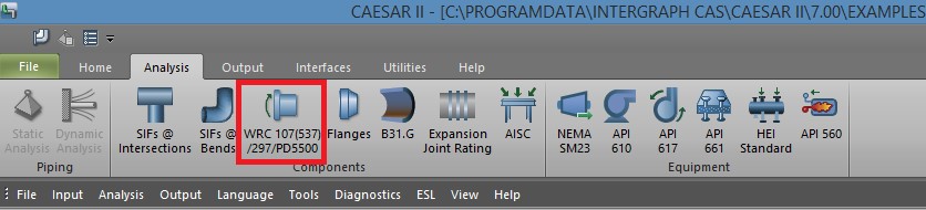
2. Look for WRC icon under your analysis tab. Click here and enter a job name in the space provided.
3. Select which one you would like to perform.
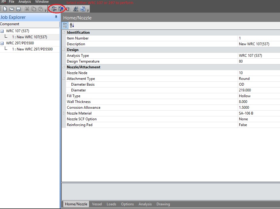
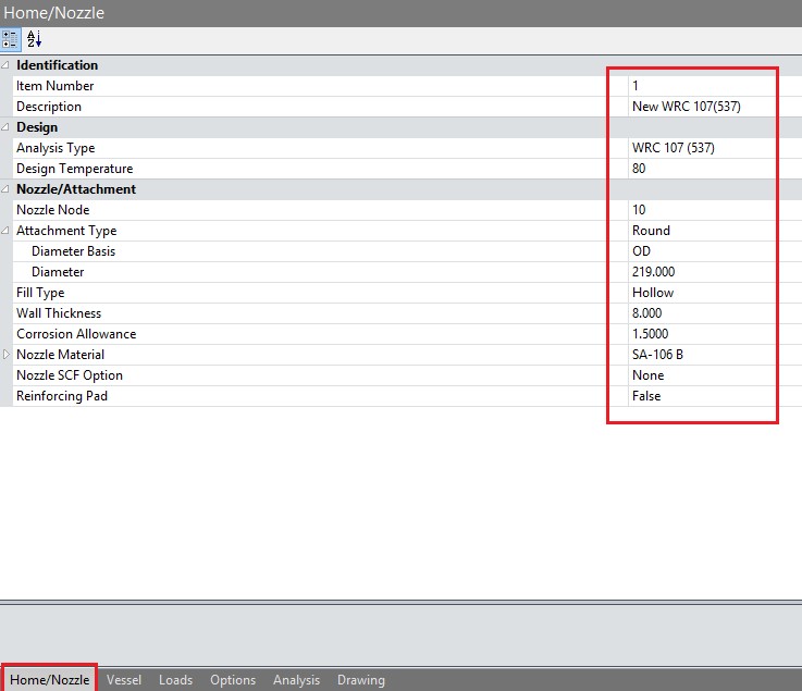
4. Give the required input for Nozzle.
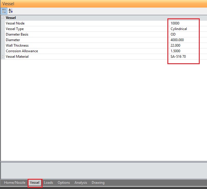
5. Give the required input for Vessel
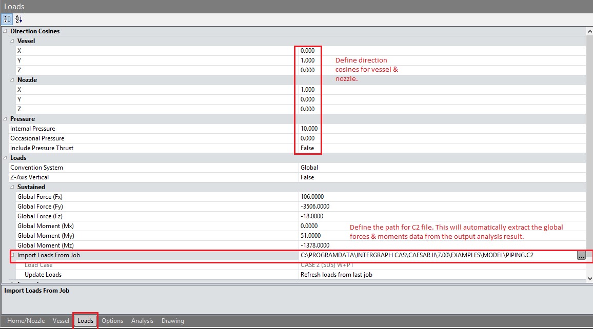
6. Input vessel and Nozzle direction cosines, Internal design pressure and load and moments values from Caesar static analysis output (Sustained, Expansion and occasional as applicable). Define path of C2 file.
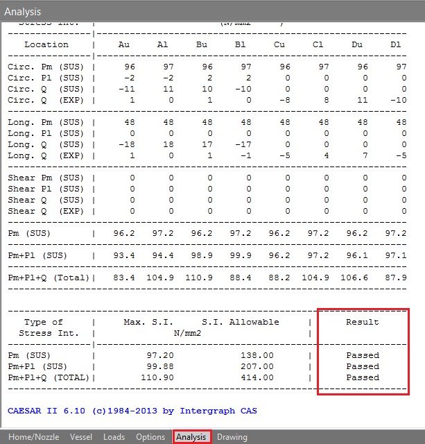
7. It is recommended to not to change any parameter under “Options” tab. Now click on analysis to read the results. Check the result for WRC analysis wether it is failed or passed.

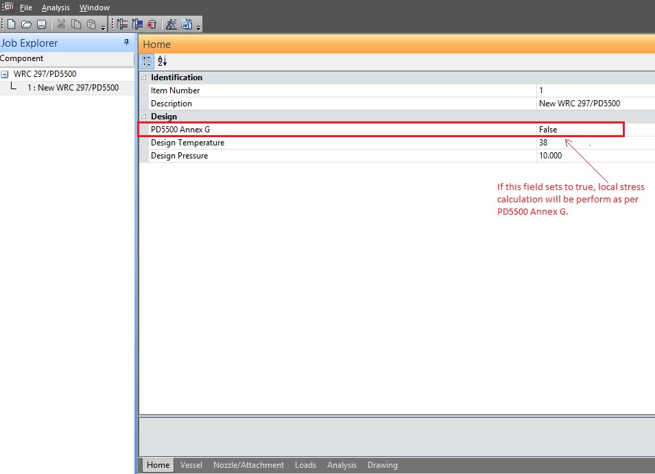
Note: – For WRC 297, If below highlighted field sets to True. The program will compute local stresses in accordance with British Standard 5500 Annex G instead of Welding Research Council Bulletin 297.